A late apex can be faster because the car is oriented toward the corner exit during the first half of the corner, allowing the driver to unwind the steering earlier than with a conventional apex and transition to a larger throttle opening sooner.
On entry, the turning radius becomes smaller and the minimum speed tends to be lower. On exit, however, the car can begin gaining speed earlier and carry that speed advantage onto the following straight. If the benefit gained on exit exceeds the loss incurred on entry, the total time from before corner entry to after corner exit becomes shorter.
In this article, I compare conventional-apex and late-apex cornering using four diagrams showing the racing lines, throttle opening, brake pedal force, steering angle, and changes in speed.
In the conceptual model, the measured section runs from Gate A on the approach straight to Gate B on the exit straight. The distance is identical in both cases. The conventional-apex line takes 5.30 seconds, while the late-apex line takes 4.90 seconds.
The late-apex line therefore covers the same distance in 0.40 seconds less.
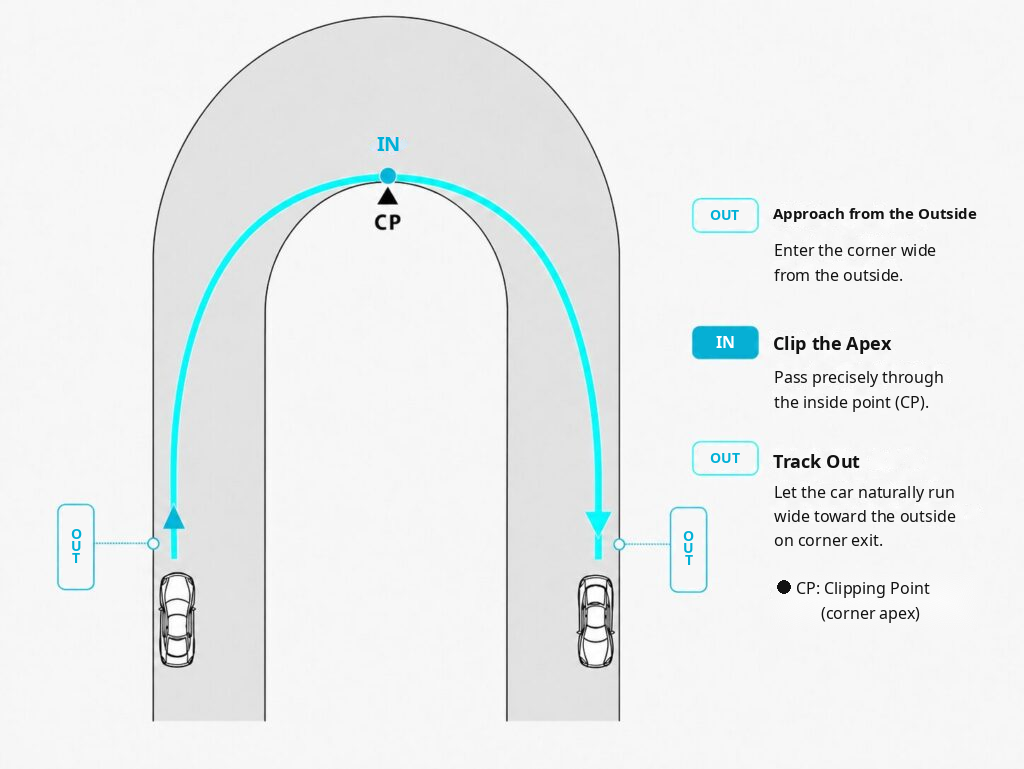
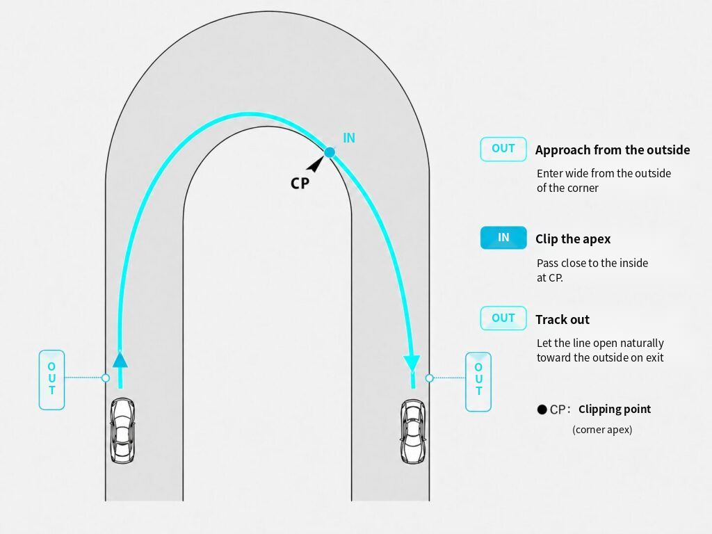
Figures 1 and 2 show the racing lines from the point where hard braking has ended and the car begins to turn, to the moment when the turning phase ends and the car enters the exit straight.
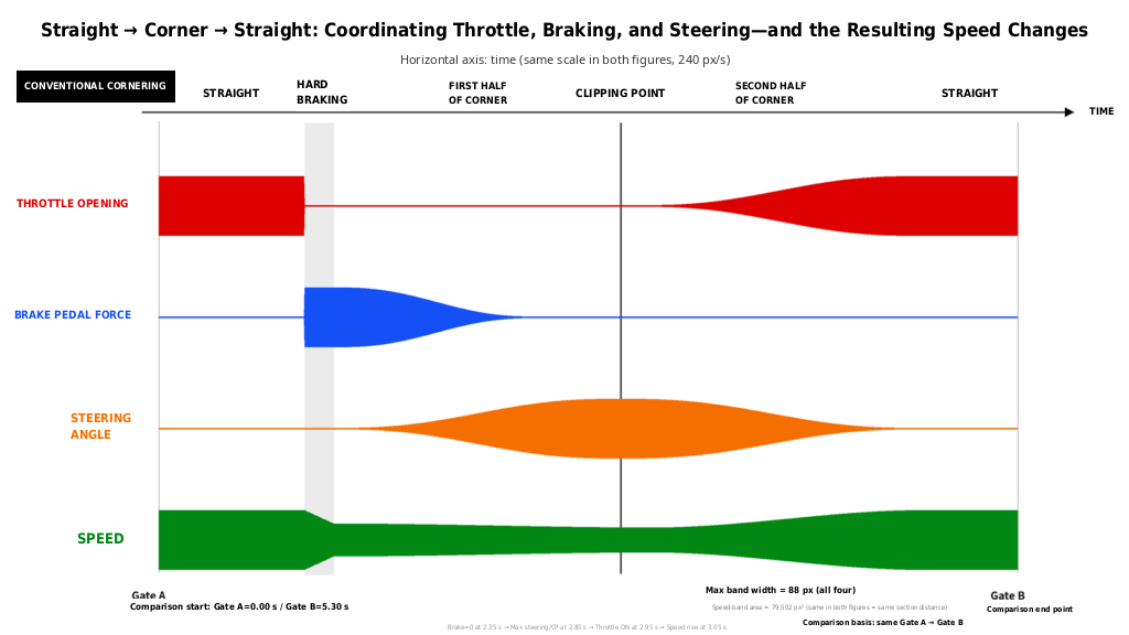
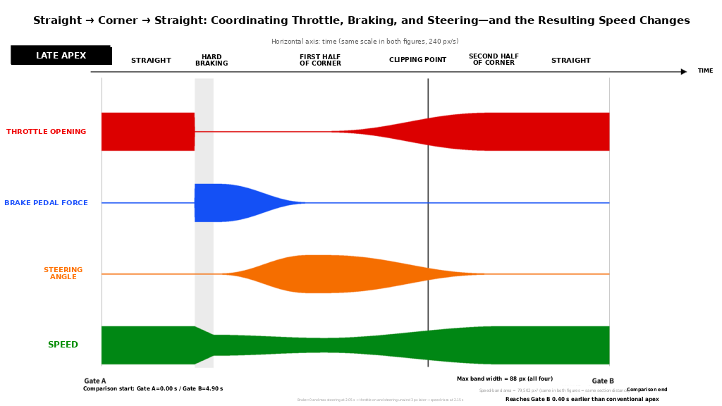
Figures 3 and 4 extend the comparison to include the straights before and after the corner. They show changes in throttle opening, brake pedal force, steering angle, and speed along a horizontal time axis.
We will now follow the sequence from the difference in racing line, to the difference in driver inputs, and finally to the resulting differences in speed and elapsed time.
Contents
The Corner Assumed in This Article
This article assumes a layout in which a long approach straight and a long exit straight are connected by a 180-degree corner with constant centerline curvature.
Factors such as gradients, banking, surface irregularities, and linked corners are omitted so that the comparison can focus on the fundamental difference between a conventional apex and a late apex.
In Figures 1 and 2, the target point placed on the inside boundary of the corner is called the clipping point, abbreviated as CP. The point on the racing line that passes closest to it is labeled IN.
Both the conventional-apex and late-apex lines are outside–inside–outside racing lines. The car moves from the outside on entry toward the inside, then opens its line toward the outside on exit.
The difference lies in where the CP is positioned and when the car is oriented toward the exit.
Fixing the Comparison Section From Gate A to Gate B
To compare the speed of conventional-apex and late-apex cornering, the starting and finishing points of the measurement must be identical.
Figures 3 and 4 therefore include two imaginary timing lines on the circuit.
The timing line on the approach straight is Gate A.
Gate A is positioned before the driver begins hard braking at the end of the straight. In both models, the same car passes Gate A at the same speed. The moment the car crosses Gate A is defined as 0.00 seconds in both diagrams.
The timing line on the exit straight is Gate B.
Gate B is positioned at the same point after both cars have exited the corner and reached full throttle with a steering angle close to zero.
The comparison therefore covers:
The same point, Gate A, on the approach straight, to the same point, Gate B, on the exit straight.
This range includes the approach straight, hard braking, the first half of the corner, the CP, the second half of the corner, and the exit straight.
By positioning Gate B on the exit straight, the comparison includes the effect of acceleration that begins inside the corner and continues after corner exit.
A Conventional Apex Places the CP Near the Middle of the Corner
Figure 1. Conventional-Apex Racing Line
After completing the hard-braking phase, the car begins turning from the outside of the entry. The driver increases steering angle while releasing brake pedal force and aims toward the CP positioned near the middle of the corner.
Near the CP, the racing line comes closest to the inside edge of the corner. Steering angle reaches its maximum around this point, while speed also approaches its minimum during the cornering sequence.
After passing the CP, the driver gradually unwinds the steering toward the outside of the exit. Throttle opening is increased as steering angle is reduced, allowing the car to gain speed toward the exit straight.
A conventional-apex line connects the first and second halves of the corner with relatively even arcs. It makes it easier to maintain a large turning radius on entry and preserve speed until around the middle of the corner.
However, a considerable turning section remains after the CP. The driver therefore needs time to unwind the steering and transition to a large throttle opening.
The process by which coordinated brake pedal force, steering angle, and throttle opening produce an outside–inside–outside line is explained in detail in the separate article, The Outside–Inside–Outside Line Is a Result | Cornering Basics Through Trail Braking and Steering Angle.
A Late Apex Orients the Car Toward the Exit Before Reaching the CP
Figure 2. Late-Apex Racing Line
The late apex is also sometimes described as a late clipping point.
With a late apex, the car remains on the outside for longer than it does with a conventional apex, and the CP is moved farther toward the exit in the direction of travel.
The car makes a substantial change in direction before reaching the CP. As a result, the turning radius during the first half of the corner becomes smaller than with a conventional apex. To make this tighter rotation possible, both entry speed and minimum speed tend to be lower.
The time lost through this reduction in speed is the cost paid on the entry side of late-apex cornering.
In return, the car begins pointing toward the exit before reaching the CP. After reaching maximum steering angle, the driver begins unwinding the steering while still approaching the CP, which also allows throttle opening to increase earlier.
By the time the car passes the CP, its racing line is already better aligned with the exit straight than it would be on a conventional-apex line. The line after the CP is closer to a straight line, allowing the car to accelerate toward the outside of the exit sooner.
With a conventional apex, maximum steering angle, minimum speed, and passage through the CP occur at almost the same time.
With a late apex, maximum steering angle and minimum speed occur before the CP. The driver then unwinds the steering and passes the CP while speed is already increasing.
This difference in sequence changes when exit acceleration can begin.
Figures 3 and 4 Show Time Progressing Horizontally
Figures 3 and 4 are conceptual diagrams showing changes in driver inputs and speed from Gate A to Gate B as time progresses from left to right.
The red band represents throttle opening.
The blue band represents brake pedal force.
The orange band represents steering angle.
The green band represents speed.
The greater the vertical thickness of a band, the larger the value at that moment.
Throttle opening, brake pedal force, steering angle, and speed are quantities measured in different units. The thickness of each band therefore represents its relative magnitude only within that individual category.
Both Figures 3 and 4 use the following horizontal scale:
1 second = 240 px
Here, px means pixels, the unit used to measure length in the diagram.
Therefore:
- 1 px corresponds to approximately 0.00417 seconds.
- 24 px corresponds to 0.10 seconds.
- 96 px corresponds to 0.40 seconds.
The two figures also use the same vertical scale. The maximum thickness of each of the four bands is standardized at 88 px.
The thickness of a band of the same color can therefore be compared directly between Figures 3 and 4.
The Area of the Speed Band Corresponds to Distance Traveled
In Figures 3 and 4, the green speed band represents the distance traveled.
The distance covered by a car is calculated by multiplying speed by time:
Distance = Speed × Time
When the car travels at a constant speed, the speed band forms a rectangle.
Its vertical thickness represents speed, and its horizontal length represents time. The area of that rectangle therefore corresponds to speed multiplied by time—in other words, distance traveled.
During actual cornering, speed changes continuously.
The green speed band can therefore be imagined as being divided into many narrow vertical slices. For each slice, we calculate:
Speed at that moment × a very short period of time
Adding all these small areas from Gate A to Gate B gives the total area of the green speed band.
The relationship in the diagram is therefore:
Area of the green speed band
= accumulation of speed × time
= a quantity corresponding to the distance traveled from Gate A to Gate B
Figures 3 and 4 use the same horizontal time scale and the same vertical speed scale.
Therefore, if the areas of the green speed bands are equal, the distance traveled from Gate A to Gate B is also equal.
When the green areas in Figures 3 and 4 are counted at the pixel level, both have the following area:
79,502 px²
The value of 79,502 px² is a relative quantity within the diagram before conversion into a real-world distance. Because both figures use the same scale, equal areas indicate equal travel distances.
In other words, Figures 3 and 4 are designed as a comparison in which the conventional-apex and late-apex lines cover the same distance, from the same Gate A to the same Gate B.
A Conventional Apex Begins Increasing Speed After Passing the CP
Figure 3. Driver Inputs and Speed With a Conventional Apex
Figure 3 shows changes in throttle opening, brake pedal force, steering angle, and speed with a conventional apex.
Gate A is defined as 0.00 seconds. The car travels along the approach straight at full throttle.
At the end of the straight, the driver closes the throttle and applies strong, short braking while keeping the steering nearly neutral. This is the rapid-deceleration phase shown in the diagram.
After the rapid-deceleration phase, the driver gradually releases brake pedal force while increasing steering angle.
The sequence in Figure 3 is as follows:
Brake pedal force reaches zero: 2.35 seconds
Maximum steering angle and CP passage: 2.85 seconds
Throttle application begins: 2.95 seconds
Speed begins increasing: 3.05 seconds
Even after brake pedal force reaches zero at 2.35 seconds, the car continues increasing steering angle as it approaches the CP.
At 2.85 seconds, steering angle reaches its maximum and the car passes the inside point near the CP. Speed is close to its minimum around this point.
The driver begins opening the throttle at 2.95 seconds, and speed begins increasing at 3.05 seconds.
Because the car continues turning after passing the CP, steering angle takes time to return toward zero. Throttle opening also increases gradually in coordination with the unwinding of the steering.
The car then enters the exit straight. After reaching full throttle and a steering angle close to zero, it crosses Gate B at 5.30 seconds.
A Late Apex Begins Increasing Speed Before the CP
Figure 4. Driver Inputs and Speed With a Late Apex
Figure 4 shows changes in driver inputs and speed with a late apex.
The basic sequence from Gate A through the hard-braking phase is the same as in Figure 3. The car travels along the approach straight at full throttle, then uses strong, short braking at the end of the straight.
With a late apex, however, the car is rotated toward the exit earlier in the first half of the corner.
The sequence in Figure 4 is as follows:
Brake pedal force reaches zero and steering angle reaches its maximum: 2.05 seconds
Throttle application and steering unwind begin 3 px later
Speed begins increasing: 2.15 seconds
The car passes the CP while accelerating
Because the horizontal scale is 1 second = 240 px, 3 px corresponds to approximately 0.013 seconds.
The driver begins unwinding the steering and opening the throttle almost immediately after reaching maximum steering angle.
By 2.15 seconds, speed has also begun to increase.
At this point, the car has not yet reached the CP, which has been moved toward the exit. The car approaches the CP while steering angle is being reduced, throttle opening is increasing, and speed is rising.
By the time the car passes the CP, the vehicle is already oriented toward the exit straight and steering angle has been reduced substantially. This allows an even larger throttle opening after the CP.
The car then enters the exit straight and reaches Gate B at 4.90 seconds.
The relationship in which throttle opening is increased as steering angle is reduced is explained in detail in the separate article, How to Reduce Corner-Exit Understeer in the GR Yaris | Steering Angle and Throttle Opening.
Creating the Same Speed-Band Area in Less Time
The comparison conditions for the conventional-apex and late-apex models can now be summarized.
The speed-band area in both diagrams is 79,502 px².
The travel distance from Gate A to Gate B is therefore the same.
What differs is the horizontal length of the time axis.
In the conventional-apex diagram, the designed horizontal length is:
5.30 seconds × 240 px/second = 1,272 px
In the late-apex diagram, it is:
4.90 seconds × 240 px/second = 1,176 px
The difference is 96 px.
96 px ÷ 240 px/second = 0.40 seconds
The conventional-apex model creates a speed-band area of 79,502 px² over 5.30 seconds.
The late-apex model creates the same speed-band area of 79,502 px² over 4.90 seconds.
The late-apex line therefore covers the same distance in 0.40 seconds less.
The required time is approximately 7.5% shorter than with the conventional apex.
Because both models cover the same distance, the average speed over the measured section is approximately 8.2% higher with the late apex.
5.30 seconds ÷ 4.90 seconds ≈ 1.082
When viewed as a geometric shape, the green band in the late-apex diagram contains the same area within a shorter horizontal width.
That represents the same travel distance being completed in less time.
Recovering the Entry-Side Loss on Exit
Looking at the first half of the corner in Figures 3 and 4, the green speed band for the late apex is thinner than the one for the conventional apex.
With a late apex, the turning radius in the first half of the corner becomes smaller because the car must be oriented toward the exit earlier. Minimum speed therefore becomes lower.
In this part of the corner, the conventional apex has the advantage.
With the late apex, steering angle reaches its maximum at 2.05 seconds. Almost immediately afterward, the driver begins unwinding the steering and opening the throttle. Speed begins increasing at 2.15 seconds.
With the conventional apex, speed does not begin increasing until 3.05 seconds.
The late-apex model therefore begins gaining speed 0.90 seconds earlier.
Because of this earlier acceleration, the green speed band becomes thicker through the second half of the corner. On the exit straight, the car reaches full throttle sooner and maintains a higher speed for longer.
The sequence that produces the time difference is as follows:
Move the CP toward the exit
→ orient the car toward the exit before reaching the CP
→ begin unwinding the steering earlier after maximum steering angle
→ increase throttle opening earlier
→ begin increasing speed earlier
→ carry the speed advantage onto the exit straight
A late apex loses time on entry because the car must reduce speed more.
During the second half of the corner and on the exit straight, that loss is recovered through earlier acceleration.
In the present diagrams, the time gained on exit exceeds the time lost on entry, allowing the car to reach Gate B 0.40 seconds earlier.
The change in speed from slow-in to acceleration-out is examined in detail in the separate article, What Does “Slow In, Fast Out” Mean? | Finding the Missing Piece in a Famous Maxim.
Conditions That Increase the Benefit of a Late Apex
The benefit of a late apex becomes larger in corners where exit acceleration can be used for a longer period.
If the exit straight is long, the speed advantage gained through earlier acceleration continues for longer. Cars with strong acceleration performance may also gain more from shifting the emphasis toward corner exit.
The position of the CP is determined by the balance between the time lost on entry and the time gained on exit.
The farther the CP is moved toward the exit, the greater the direction change required during the first half of the corner. Minimum speed also tends to become lower.
The appropriate CP is the point at which the benefit gained on exit exceeds the loss incurred on entry by the greatest amount.
If another corner follows immediately after the exit, the car’s position and attitude for the next corner will also affect the overall section time.
The optimum racing line varies according to:
- Corner radius
- Entry speed
- Length of the exit straight
- The following corner
- Vehicle characteristics
- Tires
- Surface conditions
The 0.40-second difference shown in Figures 3 and 4 is the result produced by the specific 180-degree corner, control inputs, and speed changes assumed in this conceptual model.
The actual difference in real driving will vary according to the conditions.
Summary
With a conventional apex, the CP is positioned near the middle of the corner.
This line makes it easier to maintain a larger turning radius on entry and preserve speed until around the CP. However, because a substantial turning phase remains after the CP, the driver needs time to unwind the steering and transition to a large throttle opening.
With a late apex, the CP is moved toward the exit.
The driver reduces speed in the first half of the corner and orients the car toward the exit before reaching the CP. The steering begins unwinding earlier after maximum steering angle, allowing throttle opening and speed to increase sooner.
Figures 3 and 4 compare the same measured section, from Gate A on the approach straight to Gate B on the exit straight.
The horizontal scale is:
1 second = 240 px
In the green speed band, vertical thickness represents speed and horizontal length represents time.
Its area corresponds to:
Accumulated speed × time = distance traveled
The speed-band area is 79,502 px² in both the conventional-apex and late-apex diagrams.
The elapsed times for the same travel distance are:
Conventional apex: 5.30 seconds
Late apex: 4.90 seconds
The late-apex line covers the same distance in 0.40 seconds less.
Cornering speed is not determined solely by the speed near the CP.
It is the combined result of approach-straight speed, hard braking, minimum speed during the turn, when steering begins to unwind, when throttle opening begins to increase, and how the car accelerates onto the exit straight.
A late apex shifts the distribution of speed toward the exit side of the corner and reduces the total time required to pass through the complete section, including the exit straight.
Want to know more about the author and the thinking behind this site?
→ About Rikutsu-Kone-Taro
